Skip to content
 Chamfer 101: A Complete Guide for Engineers and Manufacturers?
Are your parts arriving with dangerously sharp edges that can injure technicians? Or are you struggling with components that won't assemble easily because a pin can't locate a hole properly?
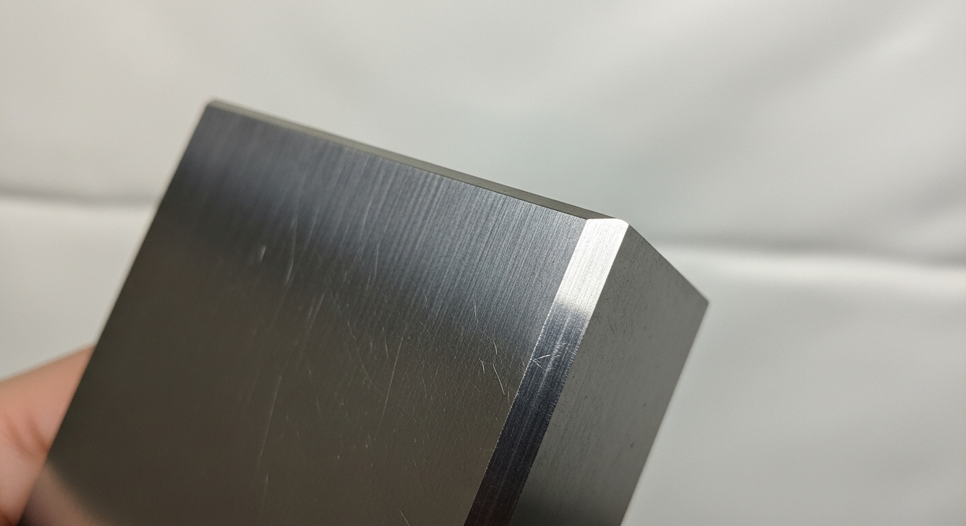
A chamfer is an angled, transitional edge created between two faces of a part, typically at 45 degrees. Its primary purposes are to break sharp edges for safety and handling, and to help guide parts for easier assembly.
As a buyer in the US, I saw how a simple, overlooked feature like a chamfer could make or break a product. Now, after running Prime Metals for over 30 years, I see it from the factory floor. A well-defined chamfer is a sign of a thoughtful design and a quality manufacturing process. It’s not just about breaking an edge; it’s a critical feature that impacts safety, function, and even cost. Let's dive into everything you need to know.
Why is a simple chamfer so critical in engineering design?
It’s easy to dismiss a chamfer as a minor detail, but that small, angled surface solves a surprising number of big problems. Ignoring it can lead to handling injuries, assembly failures, and damaged components.
A chamfer is critical because it removes a fragile, razor-sharp edge. This improves safety for handlers, prevents the edge from chipping or breaking, and creates a lead-in that guides pins, bolts, and other parts during assembly.

For Safety and Handling
The single most important reason for a chamfer is safety. A freshly machined or cut metal edge is as sharp as a knife. It can easily cut operators, technicians, or end-users. A simple note on your drawing like "Break all sharp edges" is a fundamental instruction to us to add a small chamfer or radius on all corners, making the part safe to handle throughout its lifecycle.
To Aid in Assembly
Imagine trying to push a flat-ended pin into a sharp-cornered hole of the exact same diameter. It's nearly impossible. A chamfer on the end of the pin and/or the entrance of the hole acts like a funnel. It guides the two parts together, correcting minor misalignments and making assembly faster and more reliable. This is crucial for both manual and automated assembly lines.
To Prevent Damage and Improve Durability
A sharp 90-degree corner is a weak point. It is prone to chipping, denting, or rolling over if it bumps into another object. This can create burrs that interfere with function. Adding a chamfer removes this fragile corner and replaces it with a robust, angled surface that is far more resistant to damage during shipping, handling, and operation.
How do you correctly call out a chamfer on a drawing?
How we, the manufacturer, interpret your design intent is entirely dependent on how you specify the chamfer on your technical drawing. Ambiguity here can lead to parts that don't meet your expectations.
Chamfers are typically specified in one of two ways: an angle and a distance (e.g., 1mm x 45°) or as two distances for non-45° angles (e.g., 1mm x 2mm). These can be applied to specific edges or as a general note.
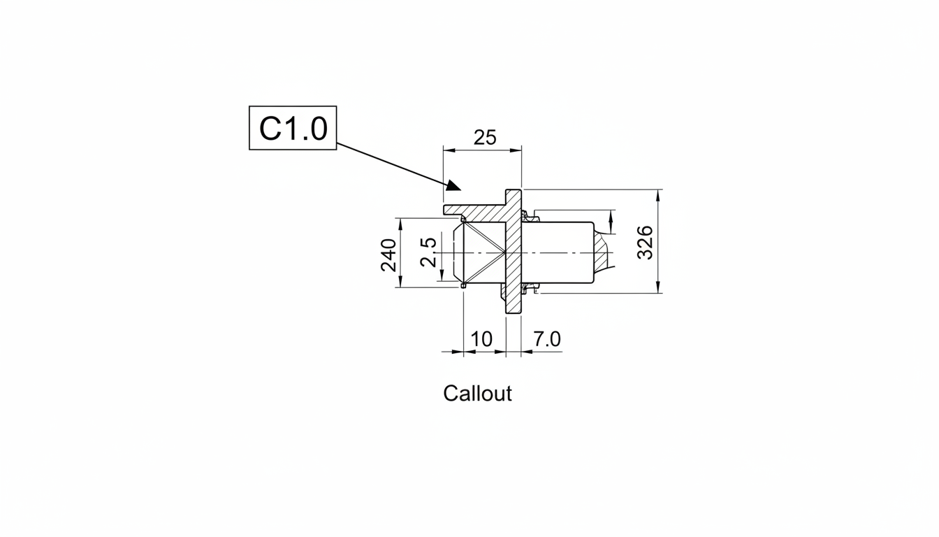
The Angle x Distance Method (e.g., 1x45° or C1)
This is the most common method, especially for 45-degree chamfers. A callout of "1 x 45°" means the chamfer extends 1mm from the corner along the axial and facial directions. It creates an isosceles triangle shape. On many drawings, this is simplified even further. A note of "C1" (or "CH 1") is universally understood by machinists to mean a 1mm x 45° chamfer. This method is clear, concise, and standard practice according to drawing standards like ISO 129-1.
The Distance x Distance Method
When a chamfer is not at 45 degrees, you must specify it using two distance measurements (e.g., 1mm x 2mm). This indicates that the chamfer extends 1mm back from the corner on one face and 2mm back on the other. This method is used when you need an asymmetrical bevel, perhaps for a specific lead-in angle or for aesthetic purposes.
General Notes and Title Block Callouts
If you want most or all edges of your part to have a uniform edge break, it's inefficient to call out every single one. Instead, you can add a general note in the title block, such as: "UNLESS OTHERWISE SPECIFIED, BREAK ALL SHARP EDGES C0.5." This tells us to apply a standard 0.5mm chamfer everywhere unless a specific edge has a different callout.
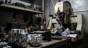
How do we actually create a chamfer in the factory?
Adding a chamfer isn't just a flick of a file. It's a planned manufacturing step that requires the right tools and processes to ensure consistency and precision, whether it's on our CNC machines or our stamping presses.
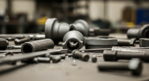
Chamfers are most commonly created through CNC machining with a specific chamfering tool. They can also be formed through grinding, stamping (coining), or mass deburring processes like tumbling for non-critical edges.
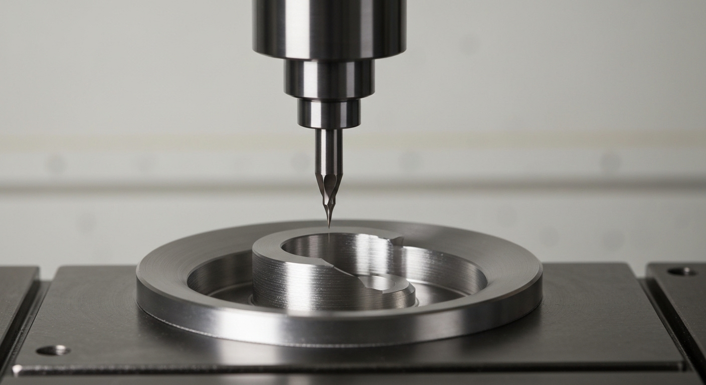
CNC Machining
This is the most precise and repeatable method. We use dedicated chamfer mills, spot drills, or even the side of an end mill to cut a precise, clean chamfer to your exact specifications. This is programmed directly into the CAM file and offers tight control over the angle and size. It's the standard method for any chamfer with a specific tolerance.
Grinding
For hardened materials or when an extremely fine surface finish and high precision are required, we may create the chamfer using a grinding wheel. The part is fixtured, and a shaped grinding wheel is used to abrade the material away, resulting in a very sharp and accurate beveled edge.
Manual and Mass Deburring
For general "edge breaking" where a precise dimension is not critical, chamfers can be created through secondary processes. In mass production of stamped parts, parts can be tumbled in a vibratory machine with ceramic media, which rolls over all a part's edges to remove burrs and create a small, inconsistent chamfer. For large parts or specific locations, a skilled technician may use a hand deburring tool or file.
| Method | Precision | Cost | Application |
|---|---|---|---|
| CNC Machining | High | Medium | Controlled, specified chamfers on any feature. |
| Grinding | Very High | High | Hardened materials, high-precision edges. |
| Tumbling | Low | Very Low | Non-critical, mass deburring of small parts. |
| Manual Deburring | Variable | Medium | One-offs, large parts, specific locations. |
Chamfer vs. Fillet: Which one is right for your design?
How we, the manufacturer, interpret your design intent is entirely dependent on how you specify the chamfer on your technical drawing. Ambiguity here can lead to parts that don't meet your expectations.
Chamfers are typically specified in one of two ways: an angle and a distance (e.g., 1mm x 45°) or as two distances for non-45° angles (e.g., 1mm x 2mm). These can be applied to specific edges or as a general note.
What is a Fillet? (The Rounded Edge)
A fillet, or radius, is a rounded corner on a part. An "internal" fillet is like the inside corner of a pocket, while an "external" fillet rounds off a sharp outside edge (often just called a "radius"). As detailed in engineering resources like Wikipedia's entry on fillets, their primary mechanical purpose is to distribute stress.
Functional Differences: Stress Concentration
This is the most critical difference. Sharp internal corners are points of high stress concentration. When a part is under load, stress flows through it, and it "bunches up" at sharp corners, which can lead to cracks and part failure. A rounded internal fillet allows the stress to flow smoothly, dramatically increasing the part's fatigue life and strength. A chamfer does little to reduce stress concentration.
Choosing the Right Feature for Your Application
Use a chamfer when:
- You need a lead-in for assembly (e.g., entrance of a hole).
- Your primary goal is safety and breaking a sharp edge.
- The appearance of a beveled edge is desired.
Use a fillet when:
- You need to reduce stress concentration on an internal corner.
- The part will be subject to vibration or cyclical loads.
- You need a smooth, rounded external edge for ergonomic or aesthetic reasons.
Can a simple chamfer specification drive up your part cost?
Yes, absolutely. Like any other feature, the way you specify a chamfer can have a significant impact on the final part cost. Over-tolerancing a non-critical feature is one of the most common ways we see costs increase unnecessarily.
An overly tight tolerance on a chamfer's dimension or angle forces us to use more precise (and slower) manufacturing and inspection methods. Additionally, placing chamfers on hard-to-reach internal features can dramatically increase programming and machining time.
The Cost of Tight Tolerances
If your drawing has a general tolerance block of +/- 0.1mm and your C0.5 chamfer falls under that, it's easy to make. But if you add a specific tolerance of +/- 0.02mm to that same chamfer, the process changes completely. It now requires more careful machining and must be verified with advanced inspection tools like an optical comparator, not just a quick visual check. Only apply tight tolerances to chamfers that are critical for function.
The Impact of Feature Accessibility
A chamfer on an outside edge of a part is simple to machine. A chamfer on the back side of a through-hole or deep inside a pocket is a different story. It may require special tooling (like a back-chamfering tool) or an additional machine setup, both of which add significant time and cost. Always consider if a chamfer in a hard-to-reach area is truly necessary.
Standard vs. Custom Chamfers
A 45-degree chamfer is standard. We have 90-degree spot drills and 45-degree chamfer mills ready to go. If you specify a 38.5-degree chamfer, it may require us to grind a custom tool or use a much slower 3D surfacing toolpath to create it. Stick to standard angles (30, 45, 60 degrees) whenever possible to keep costs down.
About the Author
My name is Kevin. I started my career in the US, sourcing industrial components for major corporations. I learned the hard way that small details on a drawing can have huge consequences on the production line. Since founding Prime Metals in 1993, I've focused on building a company that acts as a true manufacturing partner, helping our clients optimize their designs for quality, reliability, and cost.
Frequently Asked Questions (FAQs)
What is a standard chamfer size?
While there is no universal standard, common and cost-effective chamfer sizes for general edge breaking are C0.2, C0.5, and C1.0 (in millimeters). It is good practice to use a consistent size for all general chamfers on a part.
What does "break edges" mean on a drawing?
"Break edges" is a general instruction to the manufacturer to remove all sharp, 90-degree corners to make a part safe for handling. It implies a small, non-dimensioned chamfer or radius, typically around 0.2-0.5mm.
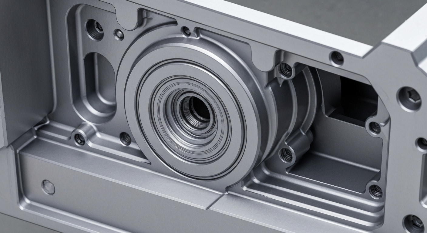
Can you chamfer internal holes?
Yes, absolutely. Chamfering the entrance to a hole is standard practice to aid assembly. We typically use a spot drill or a dedicated chamfering tool. Chamfering the back side of a hole is also possible but requires special tooling and is more costly.
Can you add a chamfer to a stamped part?
Yes. A chamfer can be "coined" into a stamped part during the stamping operation itself. This involves designing the feature into the stamping die. For existing stamped parts, chamfers can be added in a secondary machining or tumbling operation.
Turn Your Design into Reality
Understanding how a simple feature like a chamfer impacts your design's function, safety, and cost is key to effective engineering. We're here to help you translate that understanding into high-quality, finished parts.
Let our team of experts review your design and provide a manufacturing solution that meets your needs.