Skip to content
 How Do Top Suppliers Really Maintain Dimensional Integrity?
Are you sending perfect drawings with GD&T callouts, only to receive parts that don't fit in assembly? Your supplier insists they are "within spec," but the functional failures on your production line tell a different story.
Top suppliers maintain dimensional integrity by translating GD&T drawings into a formal inspection plan, using advanced tools like CMMs, and providing a detailed First Article Inspection (FAI) report that validates every single feature before starting mass production.
As someone who spent years on the buying side in the US, I know the frustration of parts that are technically "correct" but functionally useless. Now, running Prime Metals since 1993, I've built our entire quality system around one core principle: we inspect to the design intent, not just the numbers on the page. Geometric Dimensioning and Tolerancing (GD&T) isn't a suggestion; it's the language of how a part must function. Let's break down how a truly capable supplier ensures the parts you receive are the parts you designed.
What's the difference between GD&T and basic tolerances?
Are you still relying on simple plus/minus (+/-) tolerances for complex parts? This ambiguity is often the root cause of assembly problems, even when parts seem to be within the specified limits.
GD&T controls the relationship between features, like the angle of a surface or the location of a hole relative to an edge. Basic +/- tolerances only control the size of features, not their orientation or location.
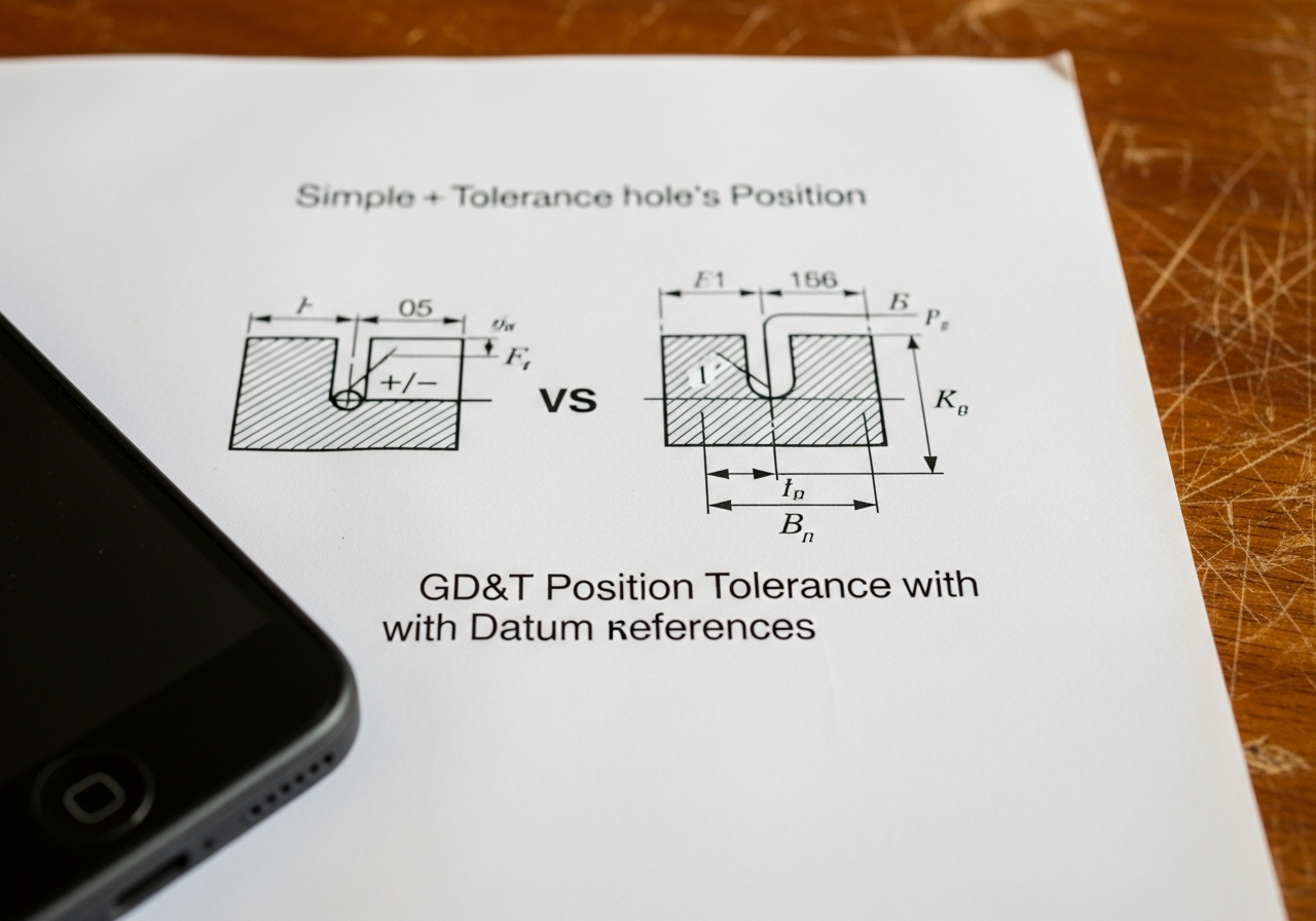
It's about function, not just size
Imagine a flange with four bolt holes. A simple +/- tolerance might allow all four holes to be the right diameter, but shifted to one side. The part would pass a basic caliper check, but it would never bolt onto its mating part. GD&T's "Position" control ensures the holes are in the correct location relative to each other and to a central feature (a datum), guaranteeing a perfect fit.
A universal engineering language
GD&T is based on an international standard, primarily ASME Y14.5. When we see a GD&T callout for Flatness, Perpendicularity, or True Position, there is no ambiguity. Our engineers in China interpret it exactly the same way your engineers in the US or Germany do. This common language eliminates guesswork and the costly errors that come with it.
Enabling better, more efficient designs
Properly applied GD&T can actually increase the tolerance zone for features, making parts easier and cheaper to manufacture while still ensuring function. For example, a "True Position" tolerance at Maximum Material Condition (MMC) gives the machinist a larger target to hit, reducing scrap rates without compromising the final assembly fit. It allows us to focus precision only where it is functionally required.
How do we translate your GD&T drawing into an inspection plan?
Receiving a drawing is just the first step. A great supplier doesn't just start making chips; they start by creating a comprehensive plan to prove the part is correct, long before the first production run.
We create an inspection plan by "ballooning" the drawing (numbering every dimension), identifying critical features and datums, and determining the precise measurement method required for each GD&T callout.
Step 1: Contract Review and "Ballooning"
The first thing our quality engineering team does is a full review. We digitally overlay a "balloon" or bubble with a unique number on every single dimension, tolerance, and note on your drawing. This becomes the master checklist for our First Article Inspection (FAI) report. It ensures nothing is missed.
Step 2: Deducing the Measurement Strategy
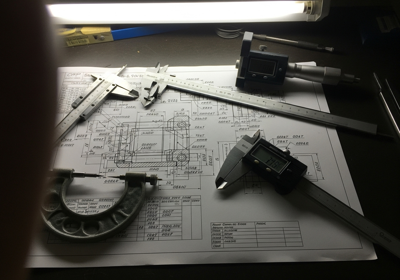
Here's where experience matters. A simple diameter can be checked with calipers. But a GD&T profile tolerance of 0.05 mm on a curved surface? That requires a Coordinate Measuring Machine (CMM). A flatness callout might need a granite surface plate and a height gauge. We document the required tool for each ballooned dimension.
Step 3: Formalizing the Plan (PPAP Element)
This entire strategy is formalized into a control plan, a key element of the Production Part Approval Process (PPAP). This document outlines the entire manufacturing and inspection process, from raw material receiving to final packaging.
| Process Stage | Key Action | Tool/Document Used |
|---|---|---|
| 1. Drawing Intake | Balloon every dimension and tolerance. | CAD Software, "Ballooned" Drawing |
| 2. Engineering Review | Identify datums and critical-to-function features. | GD&T Expertise, Team Discussion |
| 3. Method Selection | Assign the correct inspection tool for each callout. | CMM, Calipers, Optical Comparator |
| 4. Plan Creation | Document the full inspection workflow. | Quality Control Plan (QCP), FAI Sheet |
What are the key tools for accurate GD&T inspection?
Are you worried your supplier is just using basic calipers to check complex parts? For modern manufacturing, relying on outdated tools is a recipe for failure. You need a partner with the right metrology equipment.
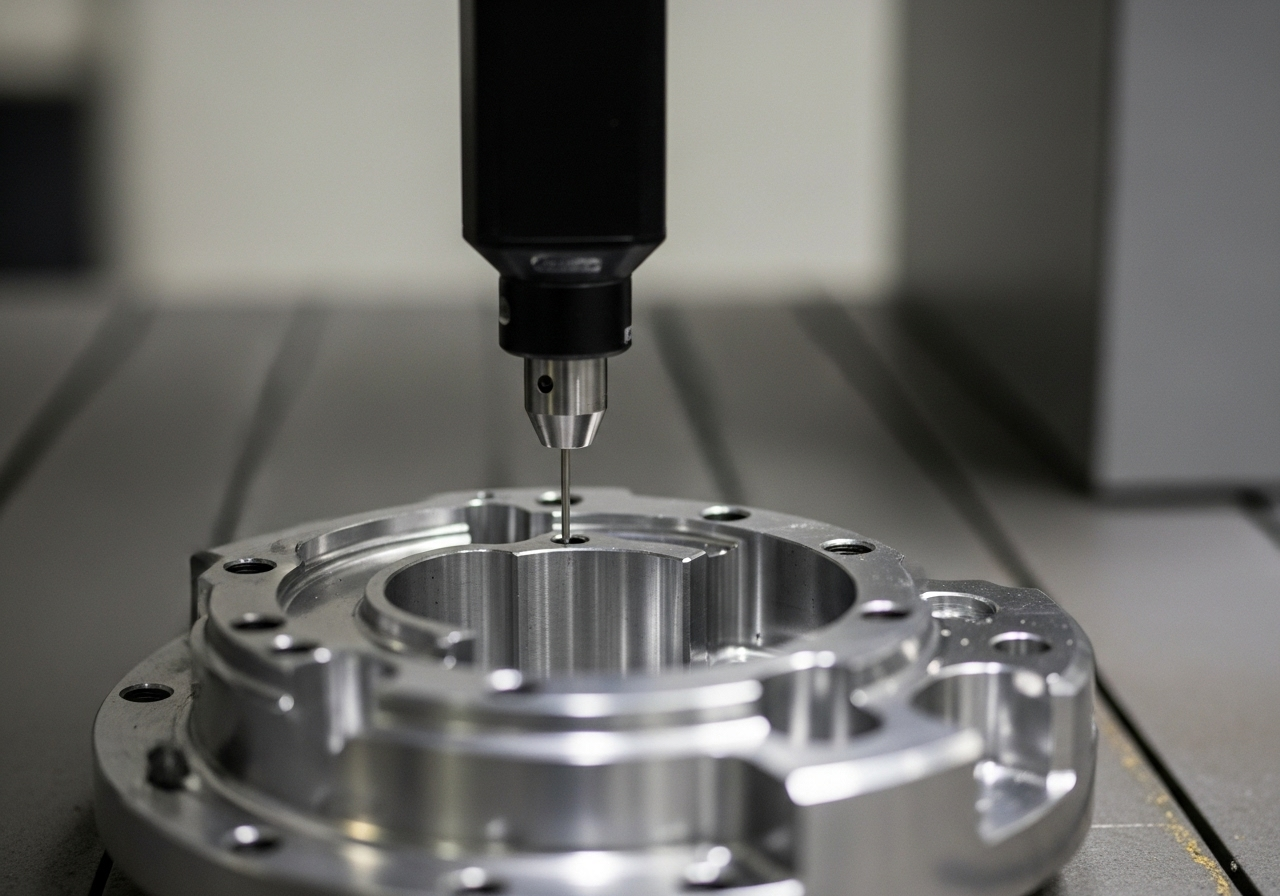
The essential tool for GD&T is the Coordinate Measuring Machine (CMM). It measures parts in 3D space to accurately verify complex geometric relationships. This is supported by optical comparators, profilometers, and calibrated hand tools.
The Workhorse: Coordinate Measuring Machine (CMM)
The CMM is the heart of any serious quality lab. It uses a highly sensitive probe to touch points on a part and construct a 3D model. From this data, it can precisely calculate GD&T features that are impossible to measure by hand, such as the concentricity of two cylinders or the profile of a surface. Our CMMs are calibrated regularly and operated in a temperature-controlled environment to ensure absolute accuracy.
For 2D and Profiles: The Optical Comparator
An optical comparator projects a magnified shadow of a part onto a screen. It's excellent for quickly checking 2D profiles, angles, and the radii of small features on parts produced by our stamping services. It provides a fast, visual confirmation that features are correct.
Hand Tools and Gauges Still Matter
Not everything requires a CMM. For less complex dimensions or for quick in-process checks, our machinists use a full suite of calibrated digital calipers, micrometers, thread gauges, and pin gauges. The key is that every tool is part of our calibration system, traced back to international standards, as required by our ISO 9001 certification.
How is a First Article Inspection (FAI) report used to guarantee conformance?
How can you be certain that the first part produced is 100% correct to your drawing before your supplier starts a run of 10,000 pieces? The FAI report is your proof.
An FAI report is a formal document that shows the measured result for every single dimension on the drawing for a sample part. It provides objective evidence that the supplier’s process is capable of making the part to spec.
Matching the Balloon to the Report
Remember the "ballooned" drawing from the planning stage? The FAI report is a table with a line item for every single balloon. Line #1 on the report corresponds directly to balloon #1 on the drawing.
What Does a Good FAI Show?
A complete FAI report includes:
- Characteristic Number: The balloon number from the drawing.
- Specification: The required dimension and tolerance from the drawing (e.g., "50.00 mm +/- 0.05").
- Measurement Result: The actual value we measured on the part (e.g., "50.02 mm").
- Pass/Fail: A clear indication if the measurement is within the tolerance band.
- Method: The tool used to get the measurement (e.g., "CMM").
We do not ship a single production part until you, the customer, have reviewed and formally approved the FAI report. This step eliminates any risk and ensures we are perfectly aligned before committing to mass production.
How do we maintain compliance throughout production?
An approved FAI is great, but how do you know the 5,000th part will be identical to the first? The key is moving from "part qualification" to "process control."
We maintain compliance by using Statistical Process Control (SPC) to monitor critical dimensions during the run, performing documented in-process inspections, and ensuring full lot traceability as mandated by our ISO 9001:2015 certification.
Statistical Process Control (SPC)
For high-volume runs, we don't just check the first and last part. We periodically sample parts during the production run and chart the measurements of critical features. This allows us to spot trends—like a cutting tool beginning to wear—and correct the process before it produces a non-conforming part.
In-Process Workstation Checks
Our operators are trained to be the first line of defense. At each workstation, there are simplified instructions and specific gauges for checking the features they are creating. This catches any potential issues immediately, rather than discovering them at the final inspection stage when it's too late.
Full Traceability
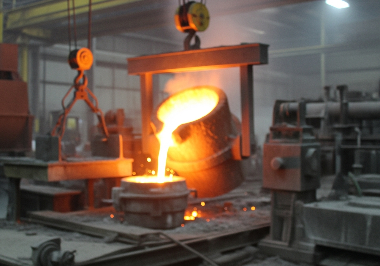
Every batch of raw material is logged. Every production run is assigned a lot number. This information follows the parts all the way to the shipping box. If there is ever an issue in the field, we can trace the part back to the exact date, machine, operator, and raw material coil it came from. This level of control is fundamental to how we manage our casting parts right through to final machining.
About the Author
My name is Kevin. I started my career in the US, sourcing industrial components for major companies like Siemens. I learned every hard lesson there is about quality control—from the frustration of a part failing a functional test despite a "good" inspection report, to the massive cost of a production line shutdown. Since 1993, I've put that experience to work here at Prime Metals, building a factory that integrates the rigorous quality systems that Western buyers demand. We don't just make parts; we deliver certified dimensional integrity.
Frequently Asked Questions (FAQs)
What is the difference between inspection and quality control?
Inspection is the act of measuring a part to see if it meets specifications. Quality Control (QC) is the entire system of processes—including inspection, SPC, and traceability—that ensures parts are consistently produced correctly. Inspection is reactive; QC is proactive.
What is a CMM and why is it important for GD&T?
A CMM, or Coordinate Measuring Machine, is a device that measures the geometry of physical objects. It's crucial for GD&T because it can measure the complex relationships between features in 3D space, like runout, profile, and true position, which are impossible to verify with hand tools.
Do all parts need GD&T?
No. Simple parts with non-critical features can often be controlled perfectly well with basic +/- tolerances. GD&T should be used where the function of a part depends on the relationship between its features—for example, where parts need to fit together, align, or move in a specific way.
What is PPAP (Production Part Approval Process)?
PPAP is a standardized process in the automotive and aerospace industries used to formally verify that a supplier's production process can consistently produce parts that meet all design requirements. The FAI report is one of the key deliverables within a PPAP submission.
Your Next Step
Ensuring dimensional integrity goes far beyond a simple pass/fail measurement. It requires a deep understanding of design intent, a robust quality system, the right metrology tools, and a commitment to transparency.
Don't leave your critical components to chance. Work with a supplier who speaks the language of GD&T as fluently as you do.